
RECORDER Manual
| |
Trigger level calibration / Full-scale SPL range
|
|
The Trigger Level Calibration tool allows to calibrate the trigger level by using a known (or otherwise fixed) reference signal. This kind of calibration is required for quantitative monitoring applications (at wind turbines for instance) that require well-defined and repeatable trigger settings.
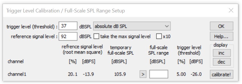
In addition to that this dialog box allows to determine or to manually enter the full-scale dB SPL range for each channel.
The Trigger Level Calibration tool adjusts the trigger level (threshold) proportionally to an externally provided reference signal. If the absolute dB SPL of the reference signal is known, then it is also possible to calibrate the trigger level directly in dB SPL.
Trigger level (threshold) : If the option relative to reference signal level is selected, enter here the desired trigger level in dB in relation to the rms level of the reference signal. 0dB would set the trigger level exactly to the level of the reference signal. -6dB would for instance set the level to half of the reference level. In case the reference signal level has been entered into the corresponding edit field and the alternative option absolute dB SPL is selected, enter here the desired trigger threshold in dB SPL.
take max signal level : If activated, the maximum registered signal level will be used for the calibration (max hold functionality). To reset the current maximum value of a particular channel, click at the X button.
The option x10 corresponds to the same option on the Configuration dialog box and should be activated in low-gain setups that require triggering on low signal levels (it will be activated automatically if the desired trigger level is low compared to the standard resolution).
toggle button1 / ref : Controls the reference signal generator of the disk microphone models through the XLR pin 5 of the UltraSoundGate 116Hnbm.
This button can also be used to control the 40 kHz reference signal generator through the XLR-4 to USB power / 2.5 mm TS adapter cable (#52007) from the TRG socket of the UltraSoundGate 116H, 116Hm, 116Hme, 416H, 816H and 1216H.
The trigger level calibration should be executed as follows:
1. Setup the recording system according to the specific needs of the application from Options/Configuration... In case the recording hardware introduces a significant DC offset, then it is recommend to activate the high-pass filter on the Configuration dialog box. In order to get a visual feedback on the current signal and trigger levels, the Display Settings option energy in f-range should be activated.
2. Start the Trigger Level calibration tool from Monitoring/Trigger level calibration...
3. Adjust the gain of the recording hardware according to the specific needs of the application (in order to prevent clipping, select the lowest gain that still provides sufficient sensitivity or an acceptable inherent noise floor).
4. Apply the reference signal to the microphone that you intend to calibrate. The rms level of this reference signal should then be shown and updated in real-time both in % (of the full-scale level or the measurement range) and dBFS. In case the absolute reference signal level [dBSPL] has been specified, the current (temporary) full-scale SPL will also be displayed. This display could also be used to adjust the full-scale range of the recording hardware (by turning its gain control knob) to a specific level (in this case, it would be appropriate to set the trigger level (from the Configuration dialog box) to a fixed value, such as 5% for instance.
5. Once the real-time display of the reference signal level has been settled after about 5 seconds (the time constant of the internal rms calculator is about 1 second), click at the associated calibrate! button, which will calculate the final trigger level (expressed in % or dBFS) according to the current reference signal level and the specified (relative or absolute) trigger level setting. At the same time, this % trigger level will be copied into corresponding edit field on the Configuration dialog box and updated on the graphic real-time display. Use the inc and dec buttons to adjust the display range of the real-time display.
6. In there are several channels, repeat the procedure for each channel (go back to paragraph 3 or 4).
7. Click Ok to close the calibration dialog box.
The full-scale SPL range calibration will be executed each time when calibrate! button is being clicked. In case a trigger level calibration is not required or desired, the temporary full-scale SPL can be copied to the full-scale SPL range edit field by clicking at the > button. If the full-scale range is already known, this value can alternatively be entered manually into the full-scale SPL range field. Once the full-scale SPL range has been determined, the numeric amplitude values shown on the real-time spectrum and level meter display (Configuration > Display Settings > Show spectrum (dBFS/dBSPL vs frequency) will represent absolute values in dB SPL. In order to get accurate SPL level measurements it is important to select the level meter mode rms level rather than peak level (dBSPL values are usually based on the roots mean square). However, in situations where averaged rms values would underestimate the signal level (when the duty cycle is less than 100%), it is recommended to use the peak level option (the difference between the rms and peak level is 3 dB in continuous sine signals).
Once the full-scale SPL range values have been defined, they will be saved automatically into to a custom-specific .wav file header chunk (titled SPL ) of each recorded .wav file, which will be read automatically by the Avisoft-SASLab Pro software in order to display absolute sound level measurements based on the calibration done in the RECORDER software.
|
|