
RECORDER Manual
| |
|
|
This dialog box allows adjusting all the parameters of the recording and triggering engine.
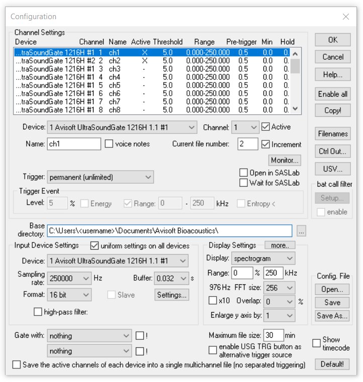
The Configuration dialog box is divided into three areas. In the top area, the channel-specific settings including trigger events can be specified. On the left bottom you will find the input device specific settings as the sampling rate and buffer properties. The display settings are located at the bottom on the right side.
Channel Settings
There is a list of all 8 virtual channels that can be managed by Avisoft-RECORDER (multi-channel version) on the top of the dialog box. The single-channel version of Avisoft-RECORDER will hide that list, because there is only one channel available. Each of these 8 virtual channels can be assigned to one of the physical sound card channels. This is done by choosing the input device (soundcard or data acquisition device) from the Device combo box and selecting the desired channel of that device from the Channel combo box. Make sure that the driver of the soundcard and data acquisition device (e.g. by National Instruments Corporation) to be used for monitoring has been installed before.
The two last entries of the Device combo-box, the WAV File and WAV File Folder options, allow to run the recording procedure from existing sound files located on disk. Select the desired file or folder by clicking at the File
button under Input Device Settings or alternatively drag the file or folder either into the Configuration dialog box or the RECORDER main window. Use the Out dev button to configure the playback output device for the selected file. This option may be useful for finding the best trigger settings for specific (sporadic) signals or for filtering .wav files that have been recorded with third-party (bat detecting) equipment. Once the WAV File or WAV File Folder option has been selected, .wav files can also be opened and started by dragging them into the RECORDER program window. While the option WAV File will process the selected file only, the option WAV File Folder will process all the files in the selected folder and its subfolders if the option include subfolders is activated. The processing of .wav files and folders can also be started by drag&drop once the corresponding Device option
has been selected. Use the option automatically skip corrupted .wav files in order to automatically reject damaged .wav files. That way the batch processing procedure will not be interrupted by corrupted files. The Device option Playback allows visualizing and processing the waveforms that are currently played through the Play menu.
The Active checkbox should be checked if you want to monitor that channel. If that checkbox is not checked, this channel will be passive and the software will only save the settings for a future activation. The Active checkbox is not available in the single-channel version (the single channel will always be active).
Open in SASLab: If this checkbox is enabled, each acquired WAV-file of the selected channel will be transferred to Avisoft-SASLab Pro once the file has been closed. To enable this mode of operation, Avisoft-SASLab Pro must have been started before. This option can only be activated for one single channel.
Wait for SASLab: In order to prevent never-ending feedback loops, this option should be activated, when Avisoft-SASLab is running in the Automatic Response mode. If this option is activated, the corresponding option Send acknowledge to Avisoft RECORDER in the SASLab Automatic Response Settings dialog must be activated too. In that mode of operation, Avisoft-RECORDER will reject triggering until SASLab has reported, that playback in response to the current file is finished.
In the Name edit box you should input a unique name for that channel. This edit box is not available in the single-channel version.
The voice notes option identifies the selected channel as a supplementary voice note track that is associated to the first active (primary) channel. If activated, the path and file names of this channel will consist of the name of first active channel plus the appended string _notexxx . In this way, the voice note files that belong to a specific (primary) .wav file can be easily indentified. On the RECORDER USGH, it is required to enable the menu option Options / Enable soundcards / audio interfaces / multichannel mode in order to access the voice notes option and to select and adjust the settings of the sound card to which the voice microphone is attached. In order to save storage space, it is recommended to use a low sample rate of for instance 11025 Hz and perhaps a bit depth of 8 bits only. If the trigger source of the voice notes channel is different from the primary channel, it is possible to create several short (sound activated) voice note files during longer lasting file of the primary channel. The created voice note files can be visualized and played in the SASLab Pro software (the option File / FileOpen Settings
> display voice notes must be enabled).
The Range or Gain list box is only available for high-speed data acquisition boards and allows selecting the input sensitivity of the channel. Please note that not all gain values listed here are necessarily supported by the specific data acquisition board. See the technical documentation of that board to find out which gain settings are valid.
The Current file number editbox shows the current file number under which the next soundfile will be saved. This entry has no effect as long as the Track Number option from the File Name Options dialog has not been activated.
The Increment checkbox should be activated if the file numbers should be incremented after completing each event file. If that checkbox is not checked, incrementing of file numbers will not take place. So, each new event would overwrite the previous one. That option is useful if you only want to transfer single sound events to Avisoft-SASLab Pro and you do not want to archive all sound events.
It is also possible to increment the file number from Avisoft-SASLab using the classification and Automatic Response option. This remote controlled incrementing allows more sophisticated signal-specific filtering of sound events. To set up this mechanism, the Open in SASLab and Wait for SASLab should be activated. In SASLab Pro appropriate Automatic Parameter Measurements and Classification settings have to be made. The Automatic Response action should be set to increment RECORDER file number. With such an arrangement, only those files containing an element, described in the classification section of SASLab, will be saved.
The Filenames button launches the File Name Options dialog box that provides a few options for the sound file names under which the sound events will be saved.
The CtrlOut button provides various mechanisms for exporting the current trigger (or file saving) state. See Control Output settings for details.
The USV button launches the USV Real-Time Monitoring Setup dialog box.
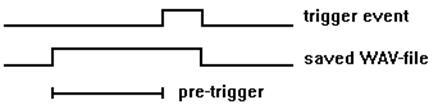
The Pretrigger editbox allows to input the desired pretrigger duration. This is the time interval that will be saved before the trigger event occurs. Keep this value as small as possible because large pre-trigger will require a large amount of RAM memory (depending on the sampling rate). Another reason for keeping the pre-trigger small are the possible gaps in the hard disk recording process when the PC is not able to save the entire pre-trigger data before the internal circular buffer is saturated. The internal temporal resolution of the pre-trigger is limited by the Buffer time specified in the Input Device Settings section.
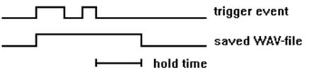
The Hold edit box specifies the hold time duration that will elapse after the last trigger event occurred before the sound file of that event will be closed. A hold time larger than zero will prevent that several consecutive short trigger events will be saved into separated files, which might be undesired because related sound elements would be cut up. The internal temporal resolution of the hold time is limited by the Buffer time specified in the Input Device Settings section.
The Hold time setting can also be used for configuring manually triggered recordings with a predefined duration (e.g. 600 s).
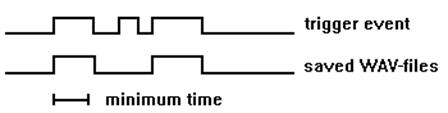
The edit box Duration > allows specifying a minimum duration for a trigger event. If the duration of the recorded sound file is shorter than this parameter, the sound event file will be skipped and overwritten by the next one. This mechanism may be useful to reject short sound events from which is known that they are out of interest. The internal temporal resolution of the minimum duration parameter is limited by the Buffer time specified in the Input Device Settings section. The Duration > threshold is applied to the size of the recorded sound file excluding the initial Pretrigger and the final Hold time. However, gaps within the acquired sound event that are shorter than the hold time setting will be ignored and will therefore not reject the sound file. The default setting for the Duration > parameter is 0.
The edit box Syllable > allows specifying a minimum duration for the syllables within the recorded sound file. If there is no syllable (a single sound element that exceeds the amplitude threshold) within the recorded sound file that is larger than specified minimum syllable duration, then the sound event file will be skipped and overwritten by the next one. In contrast to the above Duration > threshold setting, the Syllable > threshold does not take into account the hold time. This means that any silent interval within a vocalization will reset the internal syllable duration counter. The internal resolution of the Syllable > threshold is only limited by the FFT size setting and not by the Buffer duration as in the Duration > threshold mechanism.
This syllable duration threshold mechanism might help to reject unwanted short calls, while songs that consist of longer syllables will be recorded. The default setting for the Syllable > parameter is 0.
The Monitor button button launches a dialog box for activating various acoustic monitoring and measurement functions. See Monitor for details
The Trigger combo-box defines the type of event used to start and stop (trigger) this channel. The default trigger is the level of this channel, which means that the level of the same channel will be used for triggering. Alternatively, a different channel (level of channelx) can be used. This allows starting several channels simultaneously by the same trigger event of a particular channel. The whistle tracking option replaces the default level trigger by a special whistle tracking mechanism.
There is a set of other trigger events that can be used for triggering recording into WAV files:
any channel (OR): Any of the levels of the active channels will activate the trigger. The trigger events of all active channels will be linked by logic OR. This trigger option is useful for microphone array applications, where any of the microphones should be able to trigger a recording for all channels (use the option Save the active channels of each device into a single multichannel file (no separate triggering) ).
any key: Any key pressed on the keyboard will activate the trigger.
key 1 ... key 8: A user-defined keyboard key will be used for triggering. The desired key can be selected from a list box. Note that those keys that have have already defined as keyboard shortcuts (command Options / Keyboard shortcuts and popup menu
) will not function as a trigger.
button1 ... button3: One of the buttons ... on the top of the Avisoft-RECORDER window will be used for triggering. Button3 will be set automatically each time a playback is initiated (for recording responses in playback experiments).
Play button: The play button will be used for triggering. This option may be useful for recording responses in playback experiments. In such an application, an appropriate hold time should be used.
channel button: The play button  associated to the channel will be used for triggering. associated to the channel will be used for triggering.
permanent (unlimited): This : This option represents a permanent trigger that is always active. This means that the recording will start once you have clicked at the recording button (while the pause button is not active) and will continue until you click at the stop button.
permanent (limited): This option represents a permanent trigger that becomes active immediately after clicking at the red start button and continues until the defined period of time has elapsed.
interval timer: A trigger event is generated at regular time intervals. Use the Hold time field to set the duration of each shot.
time program 1...8: The channel is recorded as long as any of the pre-defined time intervals is valid. The Edit... button allows to input the desired time intervals for the selected time program (there are 8 independent time programs available). See Time Interval Definition for details.
DIO bit 0...7: The digital IN bits of a data acquisition unit is used as trigger event. By default, the trigger will be activated when selected bit is at the low state (active low logic). In the NI-DAQmx version of the software, the desired device and port numbers can be activated and defined from the NI-DAQmx DI edit field at the bottom of the dialog box (the default setting is Dev1/port0).
left-click / touch window area : A trigger event is generated by left-clicking (or tapping) the program window area below the button bar.
permanent with pretrigger: This option is similar to the option permanent (unlimited) except that it will function with the pretrigger (pre-recording).
UltraSoundGate DIN: The digital input of the Avisoft-UltraSoundGate x16x device is used as trigger event. The DIN trigger input is low-active. The ! option will change the input to high-active. The TC option will start the recording when the entered time code time has reached (this functionality requires to feed a SMPTE time code signal into the DIN input).
call class other than "?": A trigger event is generated once any of the call classes defined on the command Options/Automated call parameter settings
> Define call classes has been detected. In order to capture the corresponding call, the pretrigger duration should be selected appropriately.
.wav file playback: A trigger event is generated each time when a .wav file playback is started. This mechanism will work across instances. In order to get this work, the option create playback log file on the command Play / Settings
must be activated in the instance that performs the playback. Note that the Hold time must be set to a value that covers the duration of the playback.
joystick b1/b5 ... joystick b4/b8: One of the joystick buttons will be used for triggering. If the joystick control mechanism is not working properly, check the Game Controller settings on the Windows Control Panel (Start/System Control/Game Controller/Extended). Make sure that the desired joystick is selected as the preferred device.
joystick north, south, west, east: One of the directions pressed on the joystick will be used for triggering.
Some of these trigger events (any key, F-keys and joystick buttons) can be used in a Toggle mode. If the Toggle checkbox is activated, each hit of the key or button will change the state of the event. The first hit will switch the event on and the second hit will switch it off. If the toggle mode is disabled, the event is active as long the key or button is pressed.
The trigger sources DIO bit 0...7, UltraSoundGate DIN and joystick b1
b4 can be used in inversed logic (active high) by activating the ! option. The TC option allows to trigger on a specific timecode stamp (requires either a LANC or SMPTE timecode signal fed into a UltraSoundGate DIN input). The time stamp string is expected in the format hh:mm:ss:ff.
Trigger Event
This section defines the behavior of the trigger event generated by this channel. The trigger event is a binary signal that is derived from the FFT spectrum of the analog input signal or other digitial signals. Either the maximum amplitude of a spectral component within a frequency interval or the amount of energy within that frequency interval is compared with a threshold. If the incoming signal exceeds that threshold, the internal binary trigger event signal will become active. So, those analog trigger events may be used for a sound-activated recording mode (see Trigger above).
If the Energy checkbox is checked, the Level will be compared with the amount of energy within the specified frequency Range. If the Energy checkbox is not checked, the Level will be compared with the maximum magnitude of a spectral component within the specified frequency range. The Energy checkbox mechanism allows to distinguish between signals whose energy is spread over a wide frequency interval (noisy signals) and signals whose energy is concentrated into a narrow frequency range (pure tones, whistles).
The energy is calculated by integrating the magnitudes of the FFT spectral bins that fall within the devfined range, which is only a poor aproximation of the real energy. Use the RMS option for triggering on accurate energy values.
The Range edit boxes represent the frequency boundaries of the frequency interval to be observed. Any signal components outside that frequency range will by ignored for generating the trigger event. This allows excluding background noise and other signals that should not start a recording. This frequency discrimination is done by FFT, which has a limited frequency resolution depending on the sampling rate and FFT-length (see below). That Resolution limits the specified values for the frequency Range. If no frequency selective trigger is desired, the Range option can be disabled, which compares the waveform amplitude or the room mean square (if the RMS option is activated) with the trigger level.
Especially in configurations with many channels or high sampling rates, the disabled Range option may save computing power because the FFT is not computed. In order to prevent computing the FFT, additionally the display modes spectrogram and energy in f-range must not be activated.
If the RMS option is activated, the root means square of the waveform rather than the peak amplitude of the waveform is compared with the defined trigger level. The averaging time for calculating the RMS values is equal to the temporal resolution of the specgrogram (FFT_size * (1 - Overlap/100) / Sampling_rate).
To limit the frequency range, it is possible to activate the high-pass or custom filter in the Input Device Settings section.
The Entropy < option allows to further limit the potential trigger events in order to prevent triggering for noise signals. If this option is activated and the amplitude threshold described above is exceeded, an additional spectral flatness parameter is computed from the current FFT spectrum. Only if this instantaneous entropy parameter is below the specified threshold, the trigger event will be valid. Otherwise, the trigger event is ignored. The entropy parameter is expressed in percent. A pure (sine) tone would theoretically produce a value of 0%. A white noise signal would have 100%. Due to the properties of the windowed FFT spectra, pure tones will have entropy values significantly above 0%. Setting the entropy threshold to a value of about 35% will exclude noisy signals from triggering. The energy in f-range display shows the instantaneous entropy and the associated threshold in green. Depending on this real-time display, the entropy threshold may be modified in order to get the desired behavior.
The option reject wind/rain can help reducing undesired triggering by more or less stationary broad-band noise signals, such as wind or rain. If a broad-band signal (which is identified by calculating the Wiener entropy of the instantaneous spectra) exhibits a predefined duty cycle threshold and lasts longer than a predefined time interval (defined by an averaging time constant), the sound-activated trigger (level of this channel) will be temporarily inhibited for a user-defined hold time. The parameter settings associated with this mechanism can be adjusted from the Reject Wind/Rain Noise dialog box that can be launched from the
button:
In case the option whistle tracking has been activated, the default level trigger will be replaced by a special whistle tracking mechanism that only looks at the continuity of the peak frequencies (or frequency modulation) on the real-time spectrogram. This mode of operation can be useful for detecting soft whistle-like vocalizations that are almost buried in the background noise.
The amount of frequency modulation from one time bin to the next that should be tolerated within a valid vocalization can be defined from the edit field max change. It is expressed in spectrogram pixels and therefore depends on the currently selected FFT size and sample rate. The min duration setting rejects potential whistles that are shorter than this specified duration. In order to prevent false detections (caused by noise), this value should be as large as possible, but shorter than the typical USVs you are looking for. In order to enable the proper operation of the whistle tracking algorithm, this duration must be at least three spectrogram time bins long (one spectrogram time bin corresponds to FFT size/sample rate). There is another hold time parameter that determines how closely-spaced calls or calls with short silent gaps are treated. This hold time setting can be edited only from either the bat call filter setup dialog box or from the USV real-time monitoring setup dialog box.
The option slope allows to enter a range (between min and max) for the tolerated frequency change. Positive values correspond to rising and negative values represent falling frequencies. The resulting frequency slope range (expressed in kHz/ms) is displayed at the right margin of the dialog box. The resulting slope limits also depend on the currently selected FFT size and overlap. The option & level will additionally limit the triggering to sound events whose amplitude level exceeds the Level threshold. The Level threshold can be edited by temporarily disabling the whistle tracking option or by dragging its graphic representation on the energy in f-range display mode. The slope option can be used to reliably distinguish short downward-modulated bat echolocation calls from other noise signals such as rain drops or broad-band insect buzzes (use the command Options/Configuration management/Presets/Bat Monitoring with bat call filter to get suited parameter settings for this application).
In order to exclude any undesired noise components outside of the frequency range of the expected vocalizations, the frequency Range should be limited accordingly.
Successfully detected whistles will be indicated on the spectrogram display by red horizontal lines at the top of the display.
The Base directory edit box specifies the harddrive and directory where the acquired WAV files will be saved. The directory can either be selected from the browse button (...) next to the edit box or by direct input of the folder name into the edit field. In case the entered folder does not already exist it will be created.
Alternatively, the directory can also be selected by drag&drop into the Configuration dialog box.
The Copy button will copy the current settings from the selected channel (and the input device) to all other activated channels. This might help to accelerate setting up complex multi-channel configurations.
Input Device Settings
This section allows defining the sampling rate and buffer settings for the input devices. The parameters displayed apply to the currently selected Device, unless the option uniform settings on all devices is activated. So, to watch and edit the parameters of all input devices you need to subsequently select each of the devices.
Sampling rate: This is the sampling frequency of the selected device.
Diff: This option activates the differential input mode for data acquisition boards. For National Instruments boards use the Measurement & Automation Explorer to configure the input modes.
Gain: For decimated devices, this combo box defines a digital gain factor. See Decimation for details.
Format: Depending on the type of soundcard different bit-depths can be selected (8, 16 or 24). For high-speed data acquisition boards, the binary data format of the analog-to-digital converter has to be selected here. This will ensure that 12 bit data are shifted into the 12 most significant bits of the 16 bit data words of the .WAV file. Some A/D converters (e.g. ComputerBoards devices) supply a special offset format for signed integers. If the appropriate format is selected, the numbers are converted into the standard integer format, which is required for common 16 bit .WAV files. For the DAQCard 6062E and ines DAQ cards, the option "12 bit int" should be selected. Select "32 bit int" for the NI DSA devices (44xx).
Buffer: In order to ensure a gap-free monitoring and recording, it is necessary to provide several data buffers of a certain size to the device driver of the soundcard or audio interface. The size is expressed in seconds. This time should be long enough to bridge all other tasks of the PC while monitoring. Larger values will result in a save but more discontinuous operation of the on-line display.
Number of buffers: This is the number of buffers used for the data streaming mechanism from the device driver. Large numbers will result in a more save operation but larger memory requirements.
Slave: This option is only available in the RECORDER USGH software version and activates the slave mode for UltraSoundGate XX16H devices. The first device on the Device list box cannot be configured as a slave.
Settings :
This button (only available in the RECORDER USGH software version) launches the Advanced USGH Device Settings dialog box for configuring the UltraSoundGate XX16H devices.
File:
If the File input device is selected, this button allows selecting the .wav file to be used as input signal.
Out dev:
If the WAV File input device has been selected, this button allows you to set up the output sound device for playback during processing the selected sound file. The appearing dialog box presents a list of all available output devices. The playback rate can either be taken from the .wav file header (default) or another rate specified here. Selecting the other rate option will speed-up or slow down the original file playback speed. However, the frequency scaling for spectrograms and the trigger settings will still be based on the original sampling rate in the .wav file header. This option may be useful to adapt the sampling rate to the capabilities of the selected output (playback) device. If the playback during processing the .WAV file is not possible (due to the number of channels or a high sample rate) or not desired (in order to shorten the procedure), the last Device entry no output process as fast as possible can be selected. In this mode of operation, the .wav file will be processed at the maximum possible speed (depending on the selected Buffer duration). The processing speed can be increased by selecting a higher Buffer duration (0.5 or 1.0 s).
high-pass filter: If this option is activated, all channels of the selected device will be digitally high-pass filtered at the specified cutoff frequency. The number of taps of this FIR filter can be selected from the Taps list box. The number of taps determines the steepness of the filter. Note that this additional filter processing will increase the processor load. High sample rates, many activated channels and a large number of taps can lead to data loss (gaps in the data stream) due to the limited computing power. In such a case the number of taps should be reduced or the filter option must be deactivated.
custom filter: If this option is activated, all channels of the selected device will be digitally filtered using a custom .flf frequency response file. The .flf files are ASCII-formatted text files that contain a list of frequencies in Hz with their associated linear attenuation factors or negative logarithmic attenuation values in dB separated by space, tabulator or carriage return characters:
Sample .flf file representing a low-pass filter with a cutoff frequency of 10 kHz with linear attenuation units:
| 0 |
1.00 |
| 10000 |
1.00 |
| 10000 |
0.00 |
| 500000 |
0.00 |
Sample .flf file representing a low-pass filter with a cutoff frequency of 10 kHz with logarithmic attenuation units:
| 0 |
0 |
| 10000 |
0 |
| 10000 |
-100 |
| 500000 |
-100 |
If there is any of these factors larger than 1.0 or 0 dB, the frequency response fill be normalized to 1.0.
The .ffl files can be edited using a text editor (Notepad) or visuallly using the FIR filter tool of the SASLab Pro software (Edit > Filter > Time Domain FIR Filter... > User-defined).
The .flf files that are present in the Avisoft Bioacoustics program and documents folders can be selected from the listbox. The .flf files can alternatively selected by dragging them from the Windows File Explorer (Drag&Drop operation).
The number of taps of this FIR filter is determined by the Taps list box.
The gain list box selects a digital gain factor for compensating potential level drops caused by the filtering. Use the A option to adjust the gain automatically depending on the filter frequency response.
The custom filter functionality can be used to flatten the frequency responses of microphones. There are pre-defined compensation filters for a few electret and MEMS microphones by Syntiant, Knowles and Primo (SPV1142.flf, Knowles_FG.flf, EM179_EP3.flf).
Caution: In case the filter is applied to an UltraSoundGate channel, the state of the DIN input would not be preserved as long as the Trigger option is not set to UltraSoundGate DIN or the Keep DIN option on the Advanced USGH Device Settings dialog box is not checked. So, in order to preserve the DIN state it might be necessary to check the Keep DIN option.
channels...: When a device provides more than one channel, this button allows to activate/deactivate the filter function individually for each channel.
Display Settings
During monitoring, each of the active channels can be displayed graphically. There are the following display options:
no display: Use this option if you need to minimize the processor load in time-critical configurations (the graphic displays usually occupy a fraction of the available computing power).
waveform  : Waveform display. The display range [%] can be edited by entering the desired full-scale numerically, by clicking at the buttons : Waveform display. The display range [%] can be edited by entering the desired full-scale numerically, by clicking at the buttons  and and  or by using the mouse wheel. Over-modulation is indicated by a color change of the waveform display from yellow to red. or by using the mouse wheel. Over-modulation is indicated by a color change of the waveform display from yellow to red.
spectrogram  : Spectrogram display with a graphical representation of the trigger event frequency ranges that can be edited interactively by mouse tracking.
Display contrast [%] and display range [kHz] can be edited. The contrast can also be modified by pressing the Up and Down keys, by clicking at the buttons and
or the mouse wheel while pressing the Crtl key : Spectrogram display with a graphical representation of the trigger event frequency ranges that can be edited interactively by mouse tracking.
Display contrast [%] and display range [kHz] can be edited. The contrast can also be modified by pressing the Up and Down keys, by clicking at the buttons and
or the mouse wheel while pressing the Crtl key  . The display range [kHz] can alternatively be adjusted by using the mouse wheel. . The display range [kHz] can alternatively be adjusted by using the mouse wheel.
energy in f-range  : Energy or amplitude display within the frequency range defined in the Trigger Event section of each channel. The threshold Level specified for each trigger event channel is represented graphically and can be edited interactively by mouse tracking. : Energy or amplitude display within the frequency range defined in the Trigger Event section of each channel. The threshold Level specified for each trigger event channel is represented graphically and can be edited interactively by mouse tracking.
FFT size: This is the FFT-length used for both displaying of spectrograms and computing trigger events. This parameter determines the frequency resolution of the spectrogram display and the frequency-related trigger events.
The x10 option boost the FFT magnitudes on the spectrogram by factor 10 to better visualize soft signals in low-gain recording hardware.
Overlap: The FFT overlap setting determines the temporal resolution of the real-time spectrogram.
Enlarge y axis: This listbox allows selecting a magnification factor for the y (frequency) axis of the real-time spectrogram display.
Enlarging the frequency axis might be certainly useful when using the RECORDER software on laptops or tablet PC's with small display panels. The magnification factor can also by adjusted by using the mouse wheel while the Shift key is beeing pressed.
more: The more button launches a separate Spectrogram Settings dialog dialog box that provides additional options such as Window type and Color Palette.
Maximum file size: This option allows limiting the file size to a certain duration (specified in minutes). When this time has elapsed, the current file is closed, the file counter is incremented and a new file is created. There will be no gaps between these subsequent files. This mechanism will ensure that file sizes remain low even when recording over several hours.
This option also overcomes the file size limitation in .wav files (max. 2 GBytes).
Note that this parameter will be adjusted automatically when the maximum possible .wav file size of 2 GBytes is exceeded (depening on the entered duration, the selected sample rate and the number of channels).
The maximum file size setting will apply to all channels when the option Options > Allow individual maximum file sizes for each channel is not activated. Otherwise, it can be defined individually for each channel.
Gate with: These two list boxes allow activating up to two additional trigger criteria (linked by logical AND) that apply to all active channels. By checking the options ! behind these list boxes, that additional logic signal will be inverted (logic NOT ). If no additional criterion is desired, select nothing. The options time program will limit the sound-activated trigger operation to a few pre-defined periods of time. This might be useful if recordings should be made only for several hours (e.g. from 4am to 7am) each day. The Intervals... buttons launch the dialog box for defining the time intervals.
Save the active channels of each device into a single multichannel file (no separated triggering): If this option is activated, all channels of a multi-channel device will be saved into a single (interleaved) multi-channel .wav file. In that case the channels can of course not be triggered separately. The parameters for these channels can only be edited from the first channel of that device in the list. Threshold trigger events can also be activated from the first channel only, unless the trigger option any channel (OR) is selected. The created multichannel .wav files could afterwards still be split into a set of single-channel (mono) files in Avisoft-SASLab Pro (command Tools/Batch processing
> Split multichannel files into mono files).
Show timecode: This option activates the LANC and SMPTE timecode decoding mechanism that detects timecode signals on the UltraSoundGate DIN inputs (only available on RECORDER USG/USGH).
enable USG TRG button | left-click as alternative trigger source: If activated, this option will alternatively trigger all active channels either by pressing the UltraSoundGate trigger button (only available on RECORDER USGH) or by left-clicking (or tapping) on the program window.
USGE Devices This button defines the IP addresses and names of the USGEthernet devices. It is only available on the RECORDER USGE software.
The Default button will set all parameters to their default settings.
|
|