
RECORDER Manual
| |
|
|
This dialog box allows to set up several acoustic monitoring features.
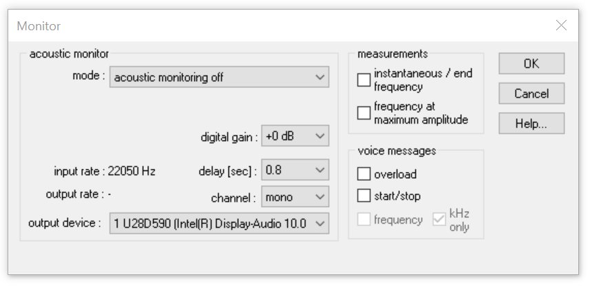
The acoustic monitor will output the incoming sound to an audio device output (speaker or headphone):
The list box mode provides the following options:
Acoustic monitoring off : The acoustic monitoring is switched off.
1:1 monitoring (output=input) : The input signal is passed unmodified to the output device. Use this option for monitoring audible (low-frequency) signals.
broad-band HF monitoring : The entire input signal is decimated and the resulting (under-sampled) signal is passed to the output device. The decimation ratio can be selected from the decimation list-box. The option auto will automatically select the best ratio for the currently selected input channel sampling rate. This mode will convert inaudible high-frequency signals into audible low-frequency signals. It is a broad band monitoring technique using the aliasing effect. The original frequency of the input signal cannot be determined from the output signal.
envelope tracking : The incoming signal is rectified and averaged in order to detect the envelope. This kind of monitoring can be used for listening to ultrasonic echolocation clicks (sonar) emitted by cetaceans. The time constant of the averaging process can be entered into the corresponding edit field. The time constant should be significantly smaller than the shortest interval between the incoming clicks. Larger values may reduce the low-frequency noise. The envelope tracking mechanism requires that the clicks to be detected have significantly steep slopes. Otherwise, the monitor output would be too soft or completely inaudible. The heterodyne monitor would be more appropriate for signals having softer slopes.
selective hetereodyne HF monitoring : A limited frequency interval of the input signal is shifted into the audible frequency domain. The list box bandwidth+- defines the bandwidth of the frequency interval to be monitored. The edit box center freq. defines the center frequency of the downshifted frequency interval. This center frequency and the bandwidth will be visualized on the real-time spectrogram display by horizontal green lines. The center frequency can be tuned in real-time by mouse or by pressing the left and right arrow keys. This mode emulates the functionality of a heterodyne bat detector. It is a narrow-band monitoring technique that only outputs the selected frequency interval. In case of limited computing power (in conjunction with high sampling rates and (or) many channels), this option should not be activated, because it will occupy a relatively high amount of the available processor capacity.
The list box output device defines the sound output device that should output the monitor signal.The list box channel defines the desired output channel of the soundcard. The options left and right will output the signal to the specified channel only (the opposite channel will be quiet).
The digital gain option can digitally amplify the digital samples that are being sent to the output audio device. Use a gain setting higher than 0 dB in order to amplify soft input signals. Note that a gain setting higher than 0 dB can potentially introduce clipping to the output signal.
The delay (sec) option allows to set an additional delay to the output signal. The minimum delay is limit option allows to set an additional delay to the output signal. The minimum delay is limited by the sound card data handling and the selected Buffer size from the configuration dialog. Small buffer sizes will decrease the minimum possible delay. Usually, the delay should be set to the minimum available value. Lager delay settings may be selected for special applications requiring echo generation.
The input rate represents the currently selected sampling rate of the sound input device. The output rate represents the sampling rate of the output device for the currently selected monitoring mode.
These measurements section provides options for real-time frequency measurements on the incoming sounds. These measurements will be updated as long as the amplitude threshold is exceeded within the specified frequency interval. This amplitude threshold and the frequency interval is defined in the Trigger Event section of the Configuration dialog (or graphically by mouse from the energy and spectrogram display). For correct measurements, it is essential to adjust the threshold properly.
instantaneous / end frequency : The instantaneous peak frequency will be measured. For signals with long duty cycles (e.g. bat echolocation calls), the displayed value represents the peak frequency at the end of the most recent pulse.
frequency at max amplitude : The frequency at the maximum amplitude of each sound event exceeding the threshold will be displayed. This mode will only be useful for relatively short sound pulses with long duty cycles (long silent intervals between sound elements, for instance bat echolocation calls).
The section voice messages provides options for issuing spoken comments on the input channel. The voice output of these options is fed into the preferred audio output device (selected from the Windows Control Panel) :
overload : In case of overload, an overload message will be issued.
start/stop : The start and stop of each sound event file will be announced.
frequency : The frequency as defined under measurements will be issued. The kHz only option will limit the precision of the issued number to integer kHz values.
The voice messages are constructed from .wav file voice pieces located in the Messages subfolder of the Avisoft Bioacoustics program folder. So, these voice messages may be replaced by your own files. All .wav files must have the same file format (sampling rate, bit-depth and channel count).
|
|