
SASLab Manual
| |
Main window : Analyze > Time axis format
|
|
The Time Axis Format dialog box allows to define the format of the time axis on the main window.
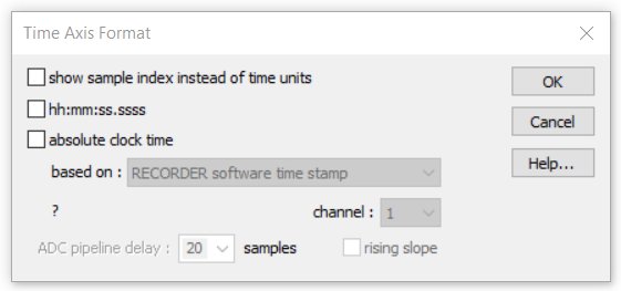
show sample index instead of time units If this option is activated, the x axis will show the sample index instead of the time in seconds.
hh:mm:ss.sssss This option activates the clock time display mode (hh:mm:ss.sssss) instead of the continuous display mode in seconds (ssss.sssss).
absolute clock time In the clock time display mode (hh:mm:ss.sssss activated), this option adds the absolute time of day time to the time scale. There are a number of options for getting this absolute time-of-day offset information:
based on:
time file created The time offset is taken from the file systems date creation entry.
time file modified The time offset is taken from the file systems date modified entry. Note that the absolute precision of the time offset will be limited by the available resolution of the file created/modified time stamp and the properties of the recording device.
Broadcast WAVE bext origination time The time offset is taken from the Broadcast WAVE bext chunk (origination time entry).
Broadcast WAVE bext timecode The time offset is taken from the Broadcast WAVE bext chunk (time reference or timecode).
RECORDER software time stamp The time offset is taken from the custom .wav file header entry created by the Avisoft RECORDER software. This option ensures a sample-precise time scale within a single monitoring session.
LANC timecode on USG DI (LSB) The time offset is taken from a serial LANC timecode signal that is stored on the USG DI track of the .wav file (recorded by using one of the UltraSoundGate units). This mode of operation requires that the LANC timecode provided by a camcorder has been recorded into one of the DIN inputs of the UltraSoundGate. Such a setup allows precisely synchronizing .wav files with video recordings. The LANC signal is provided by a number of older SONY camcorders on their LANC socket (which is usually a 2.5mm stereo TRS connector or in newer models a 10-pin A/V terminal jack). Note that not all models actually provide valid time stamps on their A/V jack. This signal can be fed into the UltraSoundGate DI input by using a custom-made interface cable that has a 3-pole 2.5 mm TRS plug at one end (with the ring pin left unconnected) and a 2-pole 2.5 mm TS plug at the other end. Such a cable is available from Avisoft Bioacoustics.
SMPTE timecode on an analog channel, SMPTE timecode on USG DI (LSB) The time offset it taken from a SMTPE timecode signal that is stored either on an analog channel or on an USG DI track. A suited SMPTE to USG DIN adapter cable is available from Avisoft Bioacoustics.
clock reference pulses on USG DI (LSB) The time offset is calculated from the number of reference pulses on the USG DI track. It is assumed that the interval of the external reference pulses is equal to one of the following values (allowing a deviation of +-10% relative to the internal sample clock):
1s, 500ms, 250ms, 100ms, 50ms, 25ms, 10ms, 5ms, 2.5ms, 1ms. The detected interval will be shown (expressed in pulses / sec) on this dialog box once the OK button has been clicked. The option rising slope will use the rising slope (low-high transition) instead of the default falling slope (high-low transition) as the reference point.
Song Meter time stamp The time offset is taken from the custom .wav file header entry (sub-chunk "wamd") created by Song Meter recorders of Wildlife Acoustics, Inc.
channel Defines the .wav file channel from which he LANC or SMPTE timecode signal is taken.
ADC pipeline delay Some analog-to-digital converters (such as those in the UltraSoundGate product family) introduce a pipeline delay relative to the digital inputs, which can be compensated here. The edit field allows entering the pipeline delay expressed by the number of samples. In the UltraSoundGate hardware, the delay is usually 20 samples.
|
|